Back to the top of the page
Contact


    Phone

    General Sales | +44 (0) 1255 446838

    Sales Support | +44 (0) 1255 423601 (Option 5)

    Transport | +44 (0) 1255 462567

    Rail | +44 (0) 1255 440291

    Industral & Commercial | +44 (0) 1255 440290

    High-Rise | +44 (0) 1255 446830

    Decking & Cladding | +44 (0) 1255 440298

    Marine | +44 (0) 1255 440297

    Email

    Sales Support | info@duracomposites.com

    Data derived from real testing not theoretical assumptions.

    We can help support your design services across all phases of the project lifecycle by providing detailed technical specifications for our award-winning product range. Our load and deflection data is available to help you make decisions based on data derived from real testing not theoretical assumptions, to ensure maximum safety for your project. Use our GRP data analysis tool known as ‘Power of Composites’ to help eliminate products which do not meet your specified Load, Span or Deflection criteria.

    Understanding Spans
    Understanding Load & Deflection
    Appropriate Loads
    Documents


    Understanding Spans

    Span is the term given to the length of a structural component that extends (or ‘spans’) between two supports. A general engineering principle is the longer the span, the deeper the structural component will have to be to safely support its self-weight and whatever it must carry.

    Clear Span

    Clear Span

    The term which describes the distance between the two inside surfaces of the span supports; i.e. the distance that is unsupported. A clear span eliminates the need to account for the bearer width used in each project and is commonly used in commercial and industrial flooring projects – including public sector buildings and balconies.

    Centre Spans

    Centre Span

    The term which describes the distance between the centres of the bearers or substrate. This is most commonly used when referring to decking and landscaping installations where historically standard timbers supports have been used.


    Understanding Load & Deflection

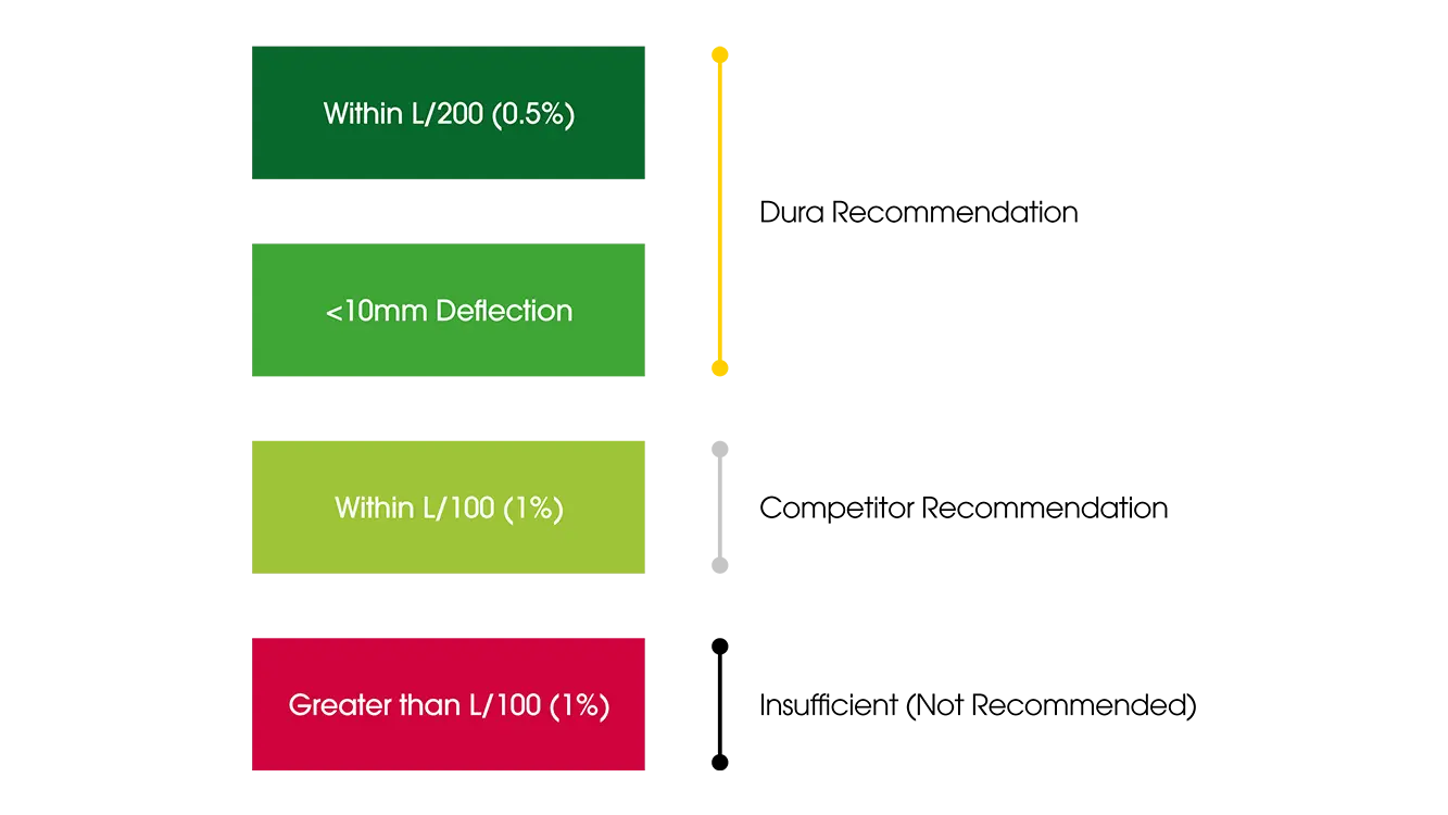
    All components of a construction project have their own structural properties which need to be carefully considered as part of the design phase. All materials will deflect or flex under load. The amount of flex depends on the magnitude of the load applied, the span, and the stiffness. Typically for better performing floors, minimal defection is desired. Maximum deflection limits are set by building codes. They are expressed as a fraction; clear span in millimetres (L) over a given limitation.

    Dura Recommend

    Deflection Examples

    Example 1: A Clear Span of 1000mm with a deflection criteria of L/200 (0.5%) has an allowable deflection of up to 5mm.

    Example 2: A Clear Span of 1000mm with a deflection criteria of L/100 (1%) has an allowable deflection of up to 10mm. Typically, a deflection of more than this for Heavy Duty Flooring is not permitted.

    This deflection limit system is applicable for various different load types.

    Load Types

    Types Of Load

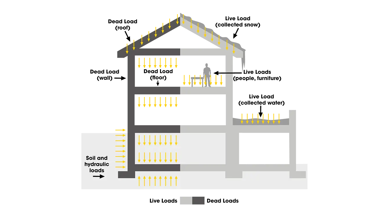
    Dead loads: include the weight of the building materials themselves, and are static and permanent. The dead load value is determined by adding together the weight of all permanently installed materials.

    Live loads: are imposed on the building and are temporary and dynamic, such as the weight of occupants, furniture or anything else that can be moved.

    To determine the minimum design values for strength, live and dead loads are added together. In order to resist these loads, all elements of the floor must have the requisite strength and stiffness, typically determined by the maximum allowable deflection of the floor, i.e. how much, it will ‘bend’ under the maximum expected load.


    Appropriate Loads

    The specification of a reduced but appropriate live load contributes to savings in the volumes of materials and, consequently, a saving in the cost of the structural frame and a reduced impact on the environment. However, this must be weighted against the fact that an increase in live load may increase the future flexibility and adaptability of the building and thereby potentially increase the life of the building.

    A live load can be expressed either as a Uniformly Distributed Load (UDL) or as one acting on a concentrated area known as a Point Load (PL). It may eventually be factored into the calculation of gravity loads. In the UK and much of Europe, live loads are expressed as kilo Newtons per square metre (kN/m²) while in the US the unit is pounds per square foot (PSF). Dura Composites uses (kN/m²) throughout for consistency and ease of comparison.

    Point Load_Illustration

    Point Load (PL)

    A point load is a concentrated force applied at a specific point on a structure. Examples of point loads include the weight of a person standing on a beam or the force exerted by a motor at a specific mounting point.

    Typical point load sizes are guided by relevant industry standards and typically range between 200-300mm, either in square shapes or circular diameters.

    The size specification is important for ensuring consistency in testing and design compliance across various applications.

    UDL_Illustration

    Uniformly Distributed Load (UDL)

    A uniformly distributed load is a force spread out over a certain length or area of a structure.

    Unlike a point load, which acts at a single point, a UDL applies force evenly across the entire length or area where it is distributed.

    UDLs are often represented as force per unit length or area. Examples of UDLs include the weight of plant equipment evenly distributed along a structural beam.